Break

physical model fabrication
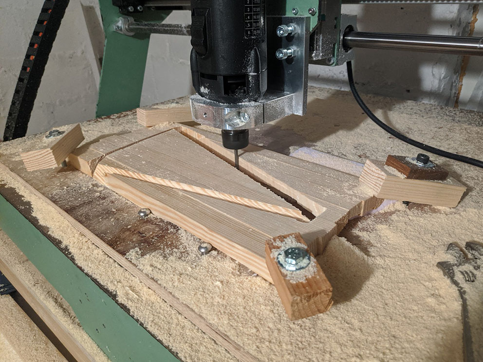
To create the polygonal shapes from the scale cleaved material, subtractive manufacturing was utilized. A CNC router cut away layers of wood 1mm deep at a time. Due to the limitations of a lightweight, home built machine, small cuts needed to be taken to create the precise edges and angles required in the final model. The machine was able to keep a speed of roughly 2500mm per minute which gave each piece a fabrication time of roughly 2 hours. The actual fabrication of each in individual piece required tailored solutions each time. First, the pieces needed to be affixed the work table of the machine. This was done using clamps bolted into inset threaded nuts that allow holding the material only by the corners, such as in the first image above. For pieces that had the cleaved texture facing downwards, shims where placed under the model to approximate a top surface perpendicular to the endmill. Insulation foam was used as it could be crushed by the clamping force, greatly increasing the holding ability of the clamps. Some pieces required a second operation. If the piece had angled edges of both slanting upwards and downwards, the modeled needed to be flipped and milled on the opposite side. This was done approximately by the endmill to a corner that was known in the digital model, then moved to the next know corner. Tracing the polygonal shape and adjusting the alignment of the piece each time until it was deemed satisfactory in its relation to the machine and thus the digital model used in generating a toolpath.
To create the polygonal shapes from the scale cleaved material, subtractive manufacturing was utilized. A CNC router cut away layers of wood 1mm deep at a time. Due to the limitations of a lightweight, home built machine, small cuts needed to be taken to create the precise edges and angles required in the final model. The machine was able to keep a speed of roughly 2500mm per minute which gave each piece a fabrication time of roughly 2 hours. The actual fabrication of each in individual piece required tailored solutions each time. First, the pieces needed to be affixed the work table of the machine. This was done using clamps bolted into inset threaded nuts that allow holding the material only by the corners, such as in the first image above. For pieces that had the cleaved texture facing downwards, shims where placed under the model to approximate a top surface perpendicular to the endmill. Insulation foam was used as it could be crushed by the clamping force, greatly increasing the holding ability of the clamps. Some pieces required a second operation. If the piece had angled edges of both slanting upwards and downwards, the modeled needed to be flipped and milled on the opposite side. This was done approximately by the endmill to a corner that was known in the digital model, then moved to the next know corner. Tracing the polygonal shape and adjusting the alignment of the piece each time until it was deemed satisfactory in its relation to the machine and thus the digital model used in generating a toolpath.


